Automated CAD drawing and layout generation
Every week, your engineering team redraws plans that always follow the same rules: a slab to form, a site to fit out, a floor to tile with gratings, a joinery product to detail. A program can produce these drawings from the project data and your engineering rules in a few seconds, leaving your drafters free for the work that really needs their judgement.
I have been developing drawing generation tools since 2008, for manufacturers and engineering firms in France and elsewhere in Europe. You deal from start to finish with the person who designs and programs yours.
What can be generated automatically
A drawing can be generated as soon as the way it is drawn can be written down as rules. That covers far more drawings than one might think:
- layouts: placing items on a plan under constraints — spacing, setbacks, no-go areas, permissible loads, orientation;
- panel and grating layouts: dividing a surface into standard panels, tiles or gratings, with the cuts and offcuts;
- drawings of parametric products: a product whose dimensions and options change with every order, but whose drawing always follows the same logic;
- the documents that follow: dimensions, bills of materials, material lists, cut lists, filled-in title blocks, sheet sets ready to print.
Input data comes from wherever it already lives: an outline drawn in the plan, an Excel or XML file exported by another program, or values typed into a dialog box.
Drawings to your standards, in your software
The output is not a frozen picture: it is a drawing in your CAD software, with your layers, dimension styles, blocks and title block. Your drafter can pick it up as if they had drawn it themselves — fix a detail, then run the generation again when an input changes.
Three principles guide these tools:
- the rules are explicit: every choice the program makes — a beam composition, a spacing, a cut — follows a rule we wrote down together, and which anyone can read;
- edge cases are flagged: when a situation falls outside the agreed rules, the tool says so rather than silently producing a wrong drawing;
- quantities follow the drawing: the material list is counted from the generated drawing, not entered separately.
Projects
These tools were developed for manufacturers and engineering firms. I keep my clients' names confidential.
Horizontal and vertical formwork
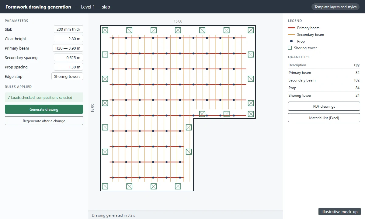
An AutoCAD add-in chooses the beam compositions and positions the props or towers, horizontally and vertically.
Scaffolding
Scaffolding is laid out on the plan, in AutoCAD, according to the trade's rules.
Solar panels
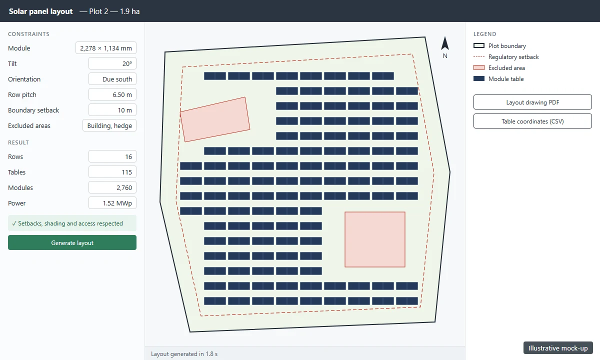
Module tables are placed automatically on a plot, respecting orientation and spacing constraints.
Gratings
The grating layout is calculated and drawn automatically from the area to be covered.
Joinery drawings
Drawings of fences, gates and railings are produced from the XML files of a commercial product configurator: the configurator handles the sale, the add-in produces the shop drawings. See also CAD product configurator development.
More examples, sorted by software, on the Projects page.
Depending on your software
Most of these tools take the form of an add-in for the CAD software your teams already use. The technologies and examples specific to each program are described on its own page:
- AutoCAD, and its compatible platforms BricsCAD and ZWCAD — see Custom AutoCAD Development;
- Inventor, for drawings and cut lists — see Custom Inventor Development;
- Revit, for batch sheets and dimensioning — see Custom Revit Development.
How a generation tool is built
- Your drawings first — We start from drawings your team has already produced, including the most unusual ones. They describe what the tool must produce better than any specification.
- The rules — Together we write down the drawing and calculation rules: what goes where, what is chosen based on what, what must be flagged.
- A prototype on your cases — The tool generates your real drawings, which we compare with the hand-drawn ones. The differences reveal the rules that were missing.
- Fixed-price quotes, in phases — A first scope, then the extension to the other cases. Each phase is ordered separately, once you have seen the result of the previous one.
The full course of a project is described on the Custom CAD & BIM automation software development page.
Autodesk Authorized Developer

WIIP is a member of the Autodesk Authorized Developer program, which gives early access to upcoming versions of Autodesk software and to the vendor's technical teams. Your generation tools are ready when the next version comes out.
 contact@wiip.fr
 (+33) 6 46 40 75 66
 8 rue du bocage, 62910 SERQUES (France)